I needed to turn a utility item yesterday, and that got me thinking about finally putting my lathe up on a proper stand. Right now, it lives on the floor of my basement, and I groan and lift it up onto my bench when I want to use it. And that's assuming there's a clean spot on my bench!
One problem with my basement shop is that the concrete floors are not level. Everything slopes to a floor drain, which will be great when there's a leak, but a pain otherwise. The shop is also quite small, so mobility is a must. This stand needs swivel casters so I can scoot it around, and adjustable feet for stability on the floor. Unlike the manufacturer's stand, this thing should also have quality storage.
[fast forward a couple of weeks]
The main carcase is a box of 3/4" plywood, 27-1/2"h x 34"w x 12". It's built with simple rabbet joints at the corners, glued and screwed together. The left side has a drawer at the top for little things, and below that a cupboard with adjustable shelves for chucks, wrenches, and other accessories. On the right is tool storage. For now, a simple vertical rack holds all the tools I have, but in the future I might have to modify this for more capacity. It might also be nice to have some sort of rack to use to set tools when I'm using them, instead of just shoving them under the lathe bed in the chips.
The box sits on 3" swivel casters, but there are outrigger legs at each end with feet that are screwed down to level and support the stand when it's in use. I've had this idea for a while, but this is the first time I've built it, and I'm very happy with the way it works. I haven't tried turning anything big and wiggly like a green bowl blank, but without adding a lot of mass to the stand, this is about as solid as it gets with the legs screwed down. Here's how they're made. The feet were cut from a 2x8. I put a fancy curve on them so you can tell I'm a classy gentleman, and they are screwed to the side of the carcase with six 2" construction screws, with the bottom about 1-1/2" from the floor when the stand is sitting on the casters. There's a 3/8" tee nut inserted into the bottom of the outrigger leg, and then a carriage bolt threaded up from below through the tee nut and up through a 3/8" hole through the leg. The head of the carriage bolt becomes the foot, and I glued some rubber feet to the bottom of them for better grip on my concrete floor. I used flat tee nuts with holes on the flange, instead of the kind with the spikes you hammer in. I fastened them into a shallow 1" mortise (made with a forstner bit) with #4 screws. The close fit of the bolt thread through the wood hole above the tee nut is intentional and adds to the rigidity of the foot. They were a little tough to turn at first, since the tee nut is never perfectly aligned with the hole, but a little wax on the threads and the action is just right so they don't tend to turn on their own. On top of the bolt, I locked two nuts together, and then turned some little 1" dia. x 3" handles out of walnut scrap. I drilled a 5/16" hole about 1/2" deep near one end of each handle, then used a chisel to enlarge that to a tight-fitting hex shape that I simply whacked onto the locked nuts with a mallet. No glue needed.
Dust collection at the lathe can be tricky. The big shavings make up most of the waste, but sanding especially can generate finer dust. I take a two-pronged approach here. I like to hang a 2-1/2" dust-collector hose right on my tool rest post. That does a good job with most of the fine stuff because it's close to the source and pulling a lot of air. Some shrouding and another dust-collector inlet underneath the lathe catch most of the big chunks that tend to fall. I also made the top overhang the cabinet about 1/2" so the debris that does escape doesn't wind up in the storage area.
Another consideration is a spot for a swing-arm lamp, either on a bracket behind the bed, or behind the tailstock. Hm.
Monday, December 31, 2012
Monday, December 10, 2012
Dining Table
I didn't finish in time for Thanksgiving. I got pretty close to having the structural work done, but the finishing took me another couple of weeks.
I used Watco 'Natural' to deepen the look and finish the base. I considered using straight boiled linseed oil, but Watco is the same thing with some kind of varnish resin added, so I think the soft fir will wind up a little tougher. A couple of coats leave the wood looking pretty natural while providing some protection. The top got several coats of Zinnser clear shellac. I probably should have just used a polyurethane varnish, but shellac is easier to fix when the inevitable happens.
I used Watco 'Natural' to deepen the look and finish the base. I considered using straight boiled linseed oil, but Watco is the same thing with some kind of varnish resin added, so I think the soft fir will wind up a little tougher. A couple of coats leave the wood looking pretty natural while providing some protection. The top got several coats of Zinnser clear shellac. I probably should have just used a polyurethane varnish, but shellac is easier to fix when the inevitable happens.
 |
| Finished Trestle Dining Table |
Tuesday, November 20, 2012
Dining Table: Trestle Structure
The support trestle is all made out of old Douglas Fir framing lumber that came out of our house, which was built in 1911. Roof rafters were 2 x 4 and will live on as the stringers and legs, a 6 x 6 porch post will become the feet, and a 2 x 6 joist from the bathroom floor will become the horizontal brace.
The stringers (aka battens) were made and attached several weeks ago, as I flattened the top.
The big post that became the feet was coated in nasty old paint, had a ton of nails in it, and has been sitting out in the weather for a couple of years. Even in that condition, I couldn't throw out a big chunk of clear lumber like that. First I pulled all the nails (one I couldn't remove got driven in deeply with a nail set) and used a thrasher ebay jack plane to clean off the paint and flatten the surface. The wood was wet from a few rainy days, so it kept the lead dust down. I cut off a couple of 26" lengths with one of my grandfather's old hand saws, and then ran those through the power planer to clean them up. After deciding how to orient the parts to hide most of the defects, I used the band saw to rip down the foot blanks to 3-1/4" x 4-1/4" x 26".
To make the curved shape of the feet, I spent some time designing patterns on hardboard, then used that to draw and cut a couple of test pieces on 2x6 lumber to show my wife and refine the shape. Once I got to something we were happy with, I used the template to draw the shape on both sides of the foot, and then cut off most of the waste on the band saw. I used a hand saw and chisels to make the sharp arrises where the flat top transitions to the curve. A paring chisel took off most of the remaining waste, and then a little quality time with the oscillating belt sander smoothed things out.
The legs are glued up from two 26" pieces of 2x4, with a 1/4" strip of walnut between them as an accent. Final blank size is 25-1/2" x 1-5/8" x 7".
I put a 1/2" x 1-1/2" x 6" mortise in the stringers. I made one with a brace and bit followed by chisel work, but roughed out the second one at the drill press with a forstner bit. The quality is the same, but the drill press is quicker. The foot got a larger mortise, 3/4" wide by 1-3/4" deep, because there's a lot more to work with on that part. Matching tenons were made in the leg blanks, cut close with the table saw and fine-tuned by hand. I have a Lie-Nielsen rabbet block plane that is my go-to tenon tuner. It can even be flipped over and used to clean up the shoulders if the wood is nice.
The cross brace is just a 2 x 6, planed down to smoothness. Big 4" x 4-5/8" long tenons were shaped on either end, fitting into 1-1/2" x 4" through mortises in the legs. Those were carefully chopped from both sides, since the edges would be visible in the finished piece. After fitting the legs to the cross brace, a tapered 1/2" x 1" (to 3/4") through mortise was made vertically through those for tapered walnut tusks to hold the assembly together.
A few more details: the ends of the horizontal brace's exposed tenons were rounded off at a 5" radius, and 1/4" was removed from the bottom of the feet to leave square pads on the ends. Most edges were eased or slightly chamfered with a block plane, to prevent splintering and keep the incidence of damaged shins to a minimum. The stringers and feet were glued onto the legs and that's all the permanent joinery on the base. Bam. Done. Now these parts can get out of the way while I finish the top.
The big question now is, will I finish in time to use this table for Thanksgiving dinner? My family's not coming up until Saturday, so I've got a couple extra days.
The stringers (aka battens) were made and attached several weeks ago, as I flattened the top.
 |
| Mmmm. Lead-based paint. |
 |
| Ah, the irony. I'm not a masochist. That stock is too long to crosscut on the table saw. |
To make the curved shape of the feet, I spent some time designing patterns on hardboard, then used that to draw and cut a couple of test pieces on 2x6 lumber to show my wife and refine the shape. Once I got to something we were happy with, I used the template to draw the shape on both sides of the foot, and then cut off most of the waste on the band saw. I used a hand saw and chisels to make the sharp arrises where the flat top transitions to the curve. A paring chisel took off most of the remaining waste, and then a little quality time with the oscillating belt sander smoothed things out.
 |
| Shaped Foot |
 |
| Roughing out mortises at the drill press |
 |
| Cleaning up a bottom leg tenon with a L-N rabbet block plane. Haven't cut the narrow shoulders yet. |
 |
| Drilling for the mortise that will hold the tusk tenon (in background) that secures the leg to the horizontal brace. |
The big question now is, will I finish in time to use this table for Thanksgiving dinner? My family's not coming up until Saturday, so I've got a couple extra days.
Thursday, November 8, 2012
Choosing a water heater
Like everything else in the world, picking a new water heater requires an unreasonable amount of research and nail biting. Here's a taste, based on a friend of mine's situation. It should be pretty easy to plug in your own numbers for usage and utility rates to do this for yourself.
Some terms:
Sorry for the units, all you socialist users of the metric system!
BTU: the amount of energy it takes to heat one pound of water 1˚F (aka British Thermal Unit)
1 kWh = 3412.3 BTU (common unit for selling electricity)
1 therm = 100k BTU (common unit for selling natural gas)
1 gallon of water weighs 8.35 lbs.
EF: efficiency rating - tells you how much incoming energy makes it into the hot water. Manufacturers like to bs around with this. For example, I believe they ignore any electrical consumption made by a gas appliance.
First, estimate your usage. For my friend, I figure one shower a day (10 min @ 2.5 gpm @ 105˚F) uses about 20 gal of hot water (the rest of the 25 gallons used is cold water mixed in the shower valve). 1 load of laundry average per day = 4 gal in her high efficiency front loader. Dishes, hand washing, etc. takes another 10 gal. So, 30 gallons a day.
How much energy is that? The average incoming cold water is about 50˚F here. If the tank is set to 120˚F, that's an increase of 70˚F, and that 30 gallons weighs 250.5 lbs. 70 x 250.5 = 17535 BTU per day.
Electric
The most basic electric water heater has an efficiency rating of about 0.90, and putting a thicker layer (3") of foam insulation gets them up to 0.95 pretty quick and cheaply. Note that the EPA no longer gives Energy Star certifications to any electric tank models except for the heat pump hybrids. The bottom line is it's too easy to get right close to the theoretical maximum EF of 1.0, so they don't feel like they need to reward anyone for that. Given how many people and programs base their buying on the Energy Star label, I think that's a mistake, but anyway... So, I'm looking at a 40 gallon model with a 12 yr warranty at Lowe's for $450. Nothing fancy. At EF 0.95, this model will consume 1974 kWh per year. (17535 BTU / 0.95 = 18458 BTU input needed per day... 18458 / 3412.3 = 5.41 kWh / day... 5.41 x 365 = 1974 kWh / yr). Our electricity is 0.11 per kWh, so operating cost is estimated at $217 a year.
Natural Gas
A very basic gas water heater is only about EF 0.59, but it's easy to find them up around 0.64. Energy Star models have to exceed 0.67, and the highest efficiency models get up to 0.70. I'm looking at a 0.67 Energy Star, 12 yr warranty model at Lowe's for $570. This model will consume 95.5 therms of natural gas per year. (17535 / 0.67 = 26172 BTU input per day... 26172 x 365 = 9,552,649 BTU / yr... divided by 100k = 95.5 therms / yr) Our natural gas is $1.08 per therm, so operating cost is estimated at $103 a year.
So even though the gas unit costs more, it should pay for itself pretty quickly, and the savings is more if you use more than the fairly minimal amounts in the examples above. But of course there are other things to think about. All-new installation of a gas unit can be very expensive. It needs an exhaust vent (chimney), or for some models they can vent via a plastic pipe out through the wall. Gas units are dependent on both the electricity (fans, controls, igniter) and gas utilities to operate. Electric just needs electricity. Electric units have no moving parts, and are much less complicated. They also are very cheap to repair (replace an element or thermostat) and the little bit of energy that they do lose ends up in your house. We live in a coolish climate, so the extra heat is a good thing for eight months of the year. Gas units dump all their excess energy out the vent, and they also poke another hole in your house's building envelope, requiring installation of a motorized vent damper if you don't want air flowing through the stack when the unit isn't operating. Electric heaters are much less likely to cause explosions if you happen to spill something flammable near them, and the carbon monoxide hazard is zero.
Friday, October 19, 2012
Dining Table: Battens and Breadboard Ends
The two parts of this table that keep the top flat are breadboard ends and the two battens that also form the top of the trestles. First I flattened the underside of the top, using a Veritas Bevel-up Jack (blade at 40˚) and my Stanley No. 4 smoother. Fir is a pain in the ass to plane, in my experience. High quality tight grained old-growth stuff isn't so bad, but this construction grade crap just loves to tear out, and it tears really deeply. It's not possible to simply fix it with a scraper because you'd have to dig a crater. With my No. 4 tuned to the limit of my abilities, I wound up with a couple of really ugly patches.
I guess I didn't resort to back-beveling the blade, so my cutting angle was no more than 45˚, but anyway the point I'm getting to is that I decided I needed a new bevel-up smoother. Going on my old rule of buying as I need (and I need to flatten this big table top), I got the full-size Veritas BU Smoother that shares blades with the other two of their BU planes I've acquired over the past few years. It's heavy, and it's a real workout to push it with a 50˚ blade in it, but so far it does seem to handle the tough grain reversals better, and it's much quicker to set up than my #4. The end grain of a couple of knots does some funky things that were handled better by a lower pitch blade, but I'm going to patch those on the top, so I don't care. I could plane around them anyway.
With the underside flat, I started making the battens. When I remodeled our upstairs bedroom, there was quite a bit of 2 x 4 framing that came out, and I kept nearly all of it, despite the nail holes and mortar and other crap I have to deal with. Here's why. Look at that grain. They were using these trees for construction lumber 100 years ago! These are rough-cut timbers, measuring pretty close to a full 2" x 4", so I can get real lumber out of them. I think I've got enough to make all the framing for the trestle if I'm careful and don't screw up.
I drew out a nice cyma and made a hardboard pattern. I then traced that out on the pieces and shaped them to the line with bandsaw, spindle sander, and some hand tools to clean up the details. I attached them to the underside of the table top with metal figure 8 connectors to allow for movement.
The breadboard ends are cherry, cut from 5/4 stock, which was barely thick enough. I flattened the ends of the top with a jointer plane run across the grain, so it would join nicely with the flat breadboard pieces.
To make the cherry end pieces I trued up the faces and one long edge of a piece of 5/4 x 39" x 4" stock, then I used a dado stack blade on the tablesaw to cut a 1/2" x 3/8" wide groove in the edge.

I used a router with a 3/4" straight bit and clamped the cherry end board as a straightedge to cut a long rabbet 1-1/2" wide x ~5/16" deep down the entire length of the end on each side, leaving a single huge tenon 3/8" thick.

With dividers, I marked out six 2" wide sections to leave full length and cut the material between to leave a 1/2" tongue, using a coping saw and sharp chisel. Then I marked out the location of the 1-1/2" mortises from the tenons on the top and made those with a 3/8" auger bit followed by some chisel work. The depth gauge in the lower left of the photo is very handy when checking mortises. That one is a General 444 that I found at a garage sale for a couple bucks. I usually set it to my tenon length plus 1/32" or so and slide it along as a go/no-go gauge. A small high spot somewhere in the bottom of a mortise can be a real hassle.

Test fitting and tuning the tenons with a rabbet block plane got the ends in place. I tend to make my mortises, cut my tenons a hair fat, and tune the joint by adjusting them if necessary. I'm going to radius the ends, but not until final assembly.

A couple of suggestions: take a small piece of scrap and put the same dado as in the end piece. You can see the one I made from a chunk of 2x6 in one of the photos. Then you can go along and test that dado against all the individual parts of the top until you get the same fit everywhere. Trying to test fit the whole thing at once doesn't really work because you can't tell where it's tight for sure. Leaving the stock over length is very very handy when it comes time to knock the end off during final fitting - otherwise there's no place to apply the mallet to remove it and you're kind of stuck.
 |
| Evil Tearout |
 |
| Rough old framing... |
 |
| ...Is tight-grained Douglas Fir |
I drew out a nice cyma and made a hardboard pattern. I then traced that out on the pieces and shaped them to the line with bandsaw, spindle sander, and some hand tools to clean up the details. I attached them to the underside of the table top with metal figure 8 connectors to allow for movement.
 |
| Final shaping of the battens |
 |
| 5/4 Cherry breadboard stock |

I used a router with a 3/4" straight bit and clamped the cherry end board as a straightedge to cut a long rabbet 1-1/2" wide x ~5/16" deep down the entire length of the end on each side, leaving a single huge tenon 3/8" thick.

With dividers, I marked out six 2" wide sections to leave full length and cut the material between to leave a 1/2" tongue, using a coping saw and sharp chisel. Then I marked out the location of the 1-1/2" mortises from the tenons on the top and made those with a 3/8" auger bit followed by some chisel work. The depth gauge in the lower left of the photo is very handy when checking mortises. That one is a General 444 that I found at a garage sale for a couple bucks. I usually set it to my tenon length plus 1/32" or so and slide it along as a go/no-go gauge. A small high spot somewhere in the bottom of a mortise can be a real hassle.

Test fitting and tuning the tenons with a rabbet block plane got the ends in place. I tend to make my mortises, cut my tenons a hair fat, and tune the joint by adjusting them if necessary. I'm going to radius the ends, but not until final assembly.

A couple of suggestions: take a small piece of scrap and put the same dado as in the end piece. You can see the one I made from a chunk of 2x6 in one of the photos. Then you can go along and test that dado against all the individual parts of the top until you get the same fit everywhere. Trying to test fit the whole thing at once doesn't really work because you can't tell where it's tight for sure. Leaving the stock over length is very very handy when it comes time to knock the end off during final fitting - otherwise there's no place to apply the mallet to remove it and you're kind of stuck.
Saturday, September 22, 2012
How to use Dividers
Dividers were a mystery to me for a while, but they are a low-tech, elegant way to accomplish very accurate work. I love stuff like that. Here are some different scenarios.
The fundamental task is to divide a length into an arbitrary number of sub-lengths. Let's say you have a board about a foot wide that you want to make nine evenly spaced holes in for a coat rack or game or something. Draw a centerline, and set the dividers for about 1/10th of the distance across the board. Just eyeball it if you want. Then start at one end of the line and walk the dividers along. When you get to the far end, whatever error you made in the setting will mean over or undershooting the end of the board. Say you're about your thumb's width over. Narrow the dividers' setting by about 1/10 of your thumb's width, and step off the line again. It might take two or three tries, but it's pretty easy to get extremely close to perfect, at which point you step down the line again, but this time press as you go to make a clear pinhole mark at each center point. Note that at no point in this do you need to measure anything. The line you're dividing can be any length, and at any angle, although it does need to be a straight line.
Once you've done it a few times, adjusting the dividers to close in on your desired value isn't fiddly. It is trial and error, but you can home in on a very accurate measurement within three or four tries. So don't get stuck in the trap that dividers are some kind of old-school imprecision thing. Let go of your fear, Luke
A common use comes up in laying out dovetails. This can be used for pins or tails (whatever you do first) but here's my tails-first approach. Make a mark a half-pin width in from each end of the board Set you dividers to about what you want a pin plus a tail width to be, and step off down the joint line from one of the half pins. Do a few trials until the last step goes off the board and lands where the far half-pin would end if it were a full pin. It doesn't need to be super exact. Then step off that distance from both ends, pushing in the points to mark out the joint.
Another use is finding the center between two points on a line. This is the simplest case of division (into two). Set the dividers for what looks like the center by eye. Take one step from either end. The mid-point of those two new marks is the center. Widen or narrow the divider setting by half the distance between those points (by eye) and try again. When the points land in the same spot, you have the center.
Wednesday, September 19, 2012
Dining Table Design and Top
Well, I got the top glued up, finally. I sliced the base of my thumb up pretty good while disassembling a handplane, so there was a week of nothing accomplished while that healed. This is by far the biggest panel glue-up I've ever attempted. Ten pieces were jointed by hand and glued up one at a time into a 7' x 3' panel. I used four Rockler 3/4" pipe clamps (with cauls) and a biscuit every 12" to help with alignment. The biscuits probably could have been further apart but I was cautious. One mistake I made was gluing the two halves together separately (into 7' x 18" sections) and then trying to glue that joint down the middle last of all. Hoisting one of the 50 lb halves up to test the joint while I planed it to match was no fun.
My wife thinks it looks good, but I think it looks like a bunch of 2x4's made into some kind of fancy picnic table. I'm planning on inlaying some dutchmen to hide a couple of knots and other ugly bits, and it will have breadboard ends, so I might be happier with it in that context.
There's around 3/16" of cup across one end, and 1/8" at the other. Cumulative errors of all the jointed surfaces show that I made a systematic error while jointing, since the whole top curves the same way. Or maybe it was the way I clamped it during glue up. I can flex it flat pretty easily with a couple of clamps and a piece of lumber, and I know a top this size will move some on it's own even if I planed it perfectly flat now in it's unrestrained state. I'm not entirely sure how to proceed though. How flat does it need to be before I put the breadboard ends on and screw stringers underneath to get it the rest of the way?
Here's the plan. I'm going to plane the bottom side with my #4 smoother and jack. That won't straighten it fully, just level the joints and smooth the surface. Then I'll install the breadboard ends and attach the stringers with figure-eight connectors, as it will be when the table is assembled. Thus, all the physical flattening devices will be on, and I can use my long planes to get the top properly flat so it looks good. As long as I don't feel like things are super stressed out when I assemble it, I think this will be ok. And like I keep telling myself - worst case, I blew $40 worth of framing lumber.
The rest of the table plan is still a little fluid, but will look something like the Sketchup rendering below. I picked up a 5/4 cherry board to make the breadboard ends and butterfly patches for a couple of spots on top, and I'm going to use walnut for a few small bits like the breadboard pins and the wedge that will hold the trestle together.
 |
| Top all glued up. This is the underside - the top has slightly fewer defects. |
There's around 3/16" of cup across one end, and 1/8" at the other. Cumulative errors of all the jointed surfaces show that I made a systematic error while jointing, since the whole top curves the same way. Or maybe it was the way I clamped it during glue up. I can flex it flat pretty easily with a couple of clamps and a piece of lumber, and I know a top this size will move some on it's own even if I planed it perfectly flat now in it's unrestrained state. I'm not entirely sure how to proceed though. How flat does it need to be before I put the breadboard ends on and screw stringers underneath to get it the rest of the way?
Here's the plan. I'm going to plane the bottom side with my #4 smoother and jack. That won't straighten it fully, just level the joints and smooth the surface. Then I'll install the breadboard ends and attach the stringers with figure-eight connectors, as it will be when the table is assembled. Thus, all the physical flattening devices will be on, and I can use my long planes to get the top properly flat so it looks good. As long as I don't feel like things are super stressed out when I assemble it, I think this will be ok. And like I keep telling myself - worst case, I blew $40 worth of framing lumber.
The rest of the table plan is still a little fluid, but will look something like the Sketchup rendering below. I picked up a 5/4 cherry board to make the breadboard ends and butterfly patches for a couple of spots on top, and I'm going to use walnut for a few small bits like the breadboard pins and the wedge that will hold the trestle together.
 |
| A fairly standard trestle table design |
El Cheapo Dining Table
I'm making us a new dining table, out of Douglas Fir. I started with 2 x 10 framing lumber from Home Depot... I found a couple in my outdoor wood pile that had been temporary supports during one of our remodeling projects. After two years outside and a trip through the planer they looked too nice to cut up for the fascia boards I had intended them for. So I went to the big orange store and picked out some more decent pieces of green, soaking wet framing lumber, and let them dry outside for awhile, then brought them to the basement for a couple of months. Then I ran them all through the planer, bringing them down to 1-1/8" thick. Today I ripped the pithy centers out of them, leaving strips of quartersawn grain ranging from 3" to 5" wide. Now I get to joint all the edges in preparation for glue-up. I don't have a powered jointer, so I'll use the tablesaw to even up the worst of it and then fine tune with my new Veritas jointer plane.
Design? I don't have a design yet. Well, it will be a trestle table, and the top will be about 7' x 3'.
 |
| Ten planks ready for jointing |
Design? I don't have a design yet. Well, it will be a trestle table, and the top will be about 7' x 3'.
Friday, August 24, 2012
Panoramic Head - prototype
A friend recently sent me a link to a panoramic photo of Mars, stitched together from a bunch of images from the Curiosity rover that landed last week. It was as close to I'm likely to get to the experience of really seeing the place, and that got me interested in making panoramic images of my own, of cool places that I have actually been to.
There is free software to stitch images together, but it works a little better if you take all the photos by pivoting the camera around a particular point in space, usually called the nodal point or entrance pupil. That point is generally near the center of the camera's lens, so a regular tripod doesn't quite cut it because it rotates around the tripod socket under the camera body. It's also typical to take photos with the camera in portrait orientation (sideways) to capture the vertical dimension as widely as possible.
Enter the panoramic head. Yeah, sure, you can buy them, but that's not how I roll. I made a bunch of sketches and here's the first iteration of a working design. The goal is to have two axes of rotation that intersect at the nodal point of the lens. This prototype is nothing fancy, just some scraps of plywood and some nuts and bolts from the hardware store. I tacked it together last night and took a quick set of pano shots of our living room. They stitched together nearly perfectly, much better than a similar set of shots I took with the tripod alone. So yay. Not so yay are some of the details. The base plate needs to be bigger, and the elevation arm can't swing down to 90˚ to take a shot straight up because of the way the camera is attached to it. I also didn't take time to rout the groove in the elevation arm that will allow adjustment for different nodal point positions.
Round two of the design will be a lot better.
There is free software to stitch images together, but it works a little better if you take all the photos by pivoting the camera around a particular point in space, usually called the nodal point or entrance pupil. That point is generally near the center of the camera's lens, so a regular tripod doesn't quite cut it because it rotates around the tripod socket under the camera body. It's also typical to take photos with the camera in portrait orientation (sideways) to capture the vertical dimension as widely as possible.
Enter the panoramic head. Yeah, sure, you can buy them, but that's not how I roll. I made a bunch of sketches and here's the first iteration of a working design. The goal is to have two axes of rotation that intersect at the nodal point of the lens. This prototype is nothing fancy, just some scraps of plywood and some nuts and bolts from the hardware store. I tacked it together last night and took a quick set of pano shots of our living room. They stitched together nearly perfectly, much better than a similar set of shots I took with the tripod alone. So yay. Not so yay are some of the details. The base plate needs to be bigger, and the elevation arm can't swing down to 90˚ to take a shot straight up because of the way the camera is attached to it. I also didn't take time to rout the groove in the elevation arm that will allow adjustment for different nodal point positions.
 |
| Canon 50D with 10-22 zoom on my plywood panoramic head. The idea is to allow pivoting about the nodal point (white) in two axes: azimuth in red, and elevation in blue. The green rotational axis is fixed. |
Round two of the design will be a lot better.
Tuesday, August 7, 2012
Why I Love Hand Tools
There seems to be a movement going over the past several years toward hand tools, at least for woodworking. So I'm definitely not the first to try to say this, but there really is a simplicity and elegance to taking care of a job with the simplest and most straightforward tool. And it's not more work. It's less. Less screwing around trying to get the height of your dado blade just right to cut the joint you're working on, and no time or materials wasted making test pieces to run across that dado blade. Less time is spent worrying about how precisely square your cabinet opening is. You can cut everything a little fat and shave parts down to perfection with a plane or chisel. You don't have to figure out how to set your miter saw to that weird acute angle, you just cut to the line with your hand saw. And on and on.
I wouldn't expect a production line environment to benefit from most hand tools. Jigs and big powerful machines are the way to go when you have to make lots of copies of anything. For the artisan or home craftsman, however, you gotta love hand tools.
My first personal example is fitting tenons. I make a lot of cabinet door frames with bridle or mortise and tenon joints. I don't worry too much about the width of the tenons. I cut them a little oversize on the tablesaw (with a tenon jig) or on the band saw, and shave them down to a nice fit in their particular mortise with a rabbetting block plane. Sort of a block plane / shoulder plane hybrid. It cuts right to the corner and shaves off a wide swath of the tenon cheek, which helps keep the surface flatter compared to a shoulder plane.
I'm currently working on a table top. At 7' x 3', very few of us can afford a drum sander or other power tool that would take on the job of flattening a slab this size. I've seen plans for a track system to run your router on, or I think there are baseplates for handheld belt sanders that help flatten large areas, or maybe you could rent a floor sander, but with a jointer plane it's a straightforward process to get it extremely, accurately flat. You may work up a sweat, but that's not a bad thing.
Monday, June 25, 2012
Bosch MX25E Quick Review
I just replaced my Dremel 6300 Multi-Max oscillating saw, which failed horribly after about an hour of runtime over several small projects. Home Depot was good enough to take it back (within the warranty period) and not make me deal with Dremel as directed on the warranty form. I took the credit and traded up to the Bosch MX25E. It's much heavier than the Dremel, which I take as a good sign. The tool was made in Malaysia, the blades were made in Europe, and the storage bag was made in China.
It came with several blades (what you get will depend on exactly which specific kit you buy) and an adapter plate that's supposed to let you use accessories from other manufacturers. The adapter plate just presents a bunch of hard, somewhat sharp points to a non-bosch blade, so you should be able to use it with anything that fits over the mounting screw regardless of the pattern of studs it was designed for. Unfortunately, you do have to completely remove the screw to change blades. Even the Dremel had a slightly faster option. It also came with a nice box to organize accessory blades in, and I prefer the heavy cloth storage bag over an inflexible plastic clamshell case.
I used it last weekend to cut the lath in the ceiling of our upstairs bathroom for a new ventilation fan. So far, so good. If you work with lath and plaster construction, these oscillating saws are great. Score and chip off the plaster with a knife, and cut the exposed lath with the saw. The high-speed oscillating action doesn't vibrate everything and damage the adjoining plaster like a sawzall or hand saw. It's house surgery with one of these things.
Bosch Rotary Hammer Angle Head Review
This here is a little writeup of the Bosch 1618580000 Angle Head for their line of rotary hammers. I bought one of these not too long ago, but had no luck even finding a decent photo of one on the web before I gave up and ordered it. Bottom line: it's solid. Made in Germany no screwing around solid piece of Bosch equipment. The body is some sort of reinforced resin casting, and what I can see of the guts is crisply-machined metal.
After removing the front handle, it slips right over the head of your Bosch rotohammer and a shaft inside engages with the chuck like a bit, except that doesn't lock in. You tighten a hex bolt to clamp it onto the body of the drill, and it can be rotated to any angle to help you reach in tight spots.
There are some caveats, one huge and the others worth knowing about. The big one is it doesn't fit all of their rotohammers. I wound up having to go buy a whole new drill to get my job done! The verbage is confusing, so either check your model number against the list of drills it says it fits, or measure the diameter of the collar behind the chuck. The inside diameter of the angle head is 42mm. My "Bulldog Xtreme" (model 11255VSR) is 50mm... So now I have two rotohammers, which makes me a tool badass, but I think I'd rather just have the extra money I had to spend.
Another issue is runtime. After ten minutes or so of continuous use, the head will get hot and you have to let it cool down. It also reduces the impact action, so don't expect to go as fast as you can with the drill itself. I think it took me about 30 minutes to drill a 5/8" diameter hole 13" deep in decent concrete, including breaks to let the head cool down.
So there you go.
 |
| Bosch Angle Head |
After removing the front handle, it slips right over the head of your Bosch rotohammer and a shaft inside engages with the chuck like a bit, except that doesn't lock in. You tighten a hex bolt to clamp it onto the body of the drill, and it can be rotated to any angle to help you reach in tight spots.
 |
| Angle Head Attached to My Rotary Hammer |
There are some caveats, one huge and the others worth knowing about. The big one is it doesn't fit all of their rotohammers. I wound up having to go buy a whole new drill to get my job done! The verbage is confusing, so either check your model number against the list of drills it says it fits, or measure the diameter of the collar behind the chuck. The inside diameter of the angle head is 42mm. My "Bulldog Xtreme" (model 11255VSR) is 50mm... So now I have two rotohammers, which makes me a tool badass, but I think I'd rather just have the extra money I had to spend.
Another issue is runtime. After ten minutes or so of continuous use, the head will get hot and you have to let it cool down. It also reduces the impact action, so don't expect to go as fast as you can with the drill itself. I think it took me about 30 minutes to drill a 5/8" diameter hole 13" deep in decent concrete, including breaks to let the head cool down.
So there you go.
Friday, June 22, 2012
Installing Euro Mudguards on a 2012 Prius
We finally got a new car. A 2012 Prius 3. Three tanks of gas in, and it's getting right about 51 mpg overall. As long as gas stays above about $3.25 a gallon, my math says it will pay for itself vs. reasonable alternative cars.

I've always put mudflaps / guards on my cars. They don't keep the dirt off, but they do reduce the amount of rock chips and tar that winds up on the side of the car. There are two styles of guards available from Toyota. The ones for the U.S. market are smallish, for some reason, but there are folks on the internet importing and selling the European version, which look much more like normal mudflaps to me. I got a set from www.juicedhybrid.com, mainly because I found a 10% off coupon code on a forum. A lot of people seem to be concerned with how difficult it will be to install these mudflaps, and what they will look like, so here's my experience. They were very easy to install, and... they look like mudflaps!
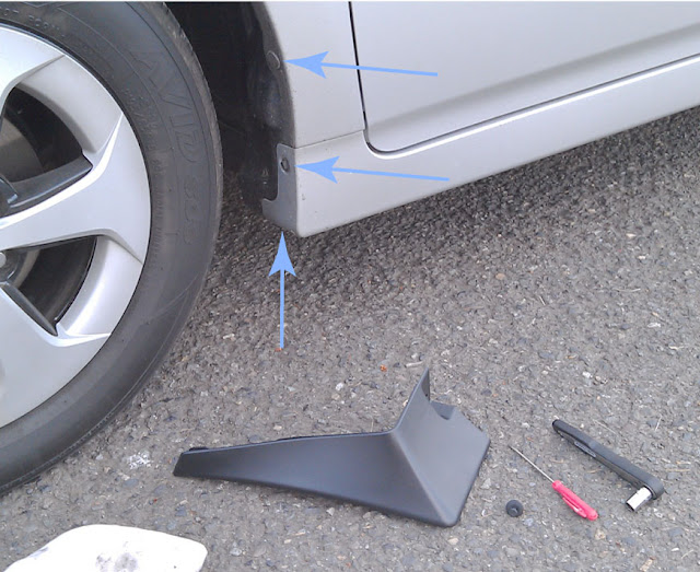
Here's a before shot of the front, with the existing fastener points indicated. VERY easy. I used a small flathead screwdriver, and a 10mm socket on a small 1/4" drive wrench. The screwdriver is used to pop up the center of the little plastic connector, and the socket undoes a couple of screws, which are re-used to attach the mudguard. The mudguards come with a new, longer plastic connector to fasten in the top hole, and that's it.

The rear is slightly more of a pain. I did it without taking the rear tire off, by using a really stubby screwdriver bit holder. If you jack up the car and pull off the tire, this job is trivially easy, and you can use regular screwdrivers and a drill to make your holes if you're more comfortable. The tools shown are a couple of stubby #2 phillips screwdrivers and a homemade tool called a birdcage awl. It's just a nail, set into a wooden handle and sharpened to a square point with a file. I use it for scratching marks, and the corners on the square point will cut a quick pilot hole in wood or plastic if the tool is twisted.

Hold the mudflap up against the car and carefully make sure it's located properly. Use the awl to reach through the lower mounting hole and scratch a horizontal line through the paint on the plastic fender / bumper. Slide one of the little metal screw clip thingies onto the plastic fender at your mark, and make a pilot hole in the center with the awl or whatever you're using.
 |
| With a short awl and really stubby screwdriver, you don't need to take the rear wheel off. |
Put the guard in place, drive a screw into the lower hole, and then locate and mark the upper hole in the same way. I know this seems fiddly, and doing them both at the same time would be faster, but this way you know everything will line up. Finally, drive the third screw in from the bottom of the guard, into the underside of the bumper. Now go find a rally course and try to spit some gravel at a Subaru.
Thursday, May 31, 2012
Water Heater Efficiency - or My Rant Against Tankless
Tankless on-demand water heaters are in vogue right now, along with most other things that purport to save money on energy costs. I think they're a silly waste of money for most people, especially folks who are trying to improve the energy efficiency of their older home. May I blather at you? It's the internet, right?
I'm a fan of a basic electric water heater. No moving parts means not much to go wrong, there's no risk of carbon monoxide poisoning, they're easy to install, and cheap. They're also nearly 100% efficient. All the electrical energy consumed goes right into heating the water. If the tank is well-insulated, the losses to the air around the water heater are small. They're especially small if the tank lives inside the thermal envelope of your home, since the heat flow is a function of the difference in temperature across the insulation. And if you live in a heating climate, the heat lost just keeps your home warmer and reduces the load on your heating system by some tiny amount during most of the year. For many people in older houses, the water heater lives in the basement, and this situation applies.
So why would you want a tankless? Natural gas is cheap... For now. I'm not sure that's a good long-term gamble. Big families that need a lot of hot water in a short period of time might want a tankless. The most compelling argument for me is the essentially unlimited flow of hot water you can get out of on-demand units. But I view this as a luxury upgrade, not an energy saver.
What happens if the power goes out? A tank heater will stay hot for a very long time, and you can use the hot water in it as long as gravity keeps working and pushing water into your pipes from the storage tank you likely rely on.
Many of the statistics you can easily look up are misleading, in my opinion. Everybody focuses on the energy factor of the unit, but it's a lot more complicated. The waste heat from a gas appliance goes out the flue. The waste heat from an electric appliance stays in the building, and there's no vent to leak air in and out of your house, so even if you could get a gas unit with the same energy factor, the real impact is different.
Tuesday, April 24, 2012
Mud Room Armoire
We need a piece of storage furniture for the mud room / laundry room entry area. Right now we have a junky old metal shelf, piled with bike gear, swim gear, and other stuff. There's no place to hang jackets or backpacks, or organize all the gear.
After measuring the space and making some quick Sketchup models, this is where I'm at.
 It's a little hard to tell from the perspective, but the front doors are asymmetric. The left door is narrower by a bit. I'm leaning toward the version on the right, with two sets of cupboard doors, and adjustable shelves inside. I envision a hanger rod across on the right side of the upper cupboard, and maybe a stack of adjustable shelving behind the smaller left door. Overall dimensions are about 36" wide, 69" high, and 20" deep. I'm having a hard time choosing the wood. When I drew it I was thinking about walnut for the frames and trim (brown) and alder for the panels (tan).
The next step is to mock it up full size on construction paper. I'll probably tack together a light frame to hold up the paper and really get a feel for how it will sit in the house.
After measuring the space and making some quick Sketchup models, this is where I'm at.

The next step is to mock it up full size on construction paper. I'll probably tack together a light frame to hold up the paper and really get a feel for how it will sit in the house.
Thursday, April 19, 2012
...In Which I Start Woodturning
As my reward for ten weeks of toil on the (soon to be) baby's room, I ordered myself a Delta 46-460 Midi Lathe last week. It came in a few days ago, I picked it up yesterday, hauled it down to the basement last night, and gave it a test drive. The last time I touched a lathe was in about 1985, and I don't think I did anything constructive with it. I intend to use it for tool handles, cabinet pull knobs, and stuff like that. I really didn't want to spend as much as I did, I just wanted a little tiny lathe, but the small ones are all fairly crappy products, made in China, and I couldn't do it.
I did a lot of research and still spent quite a while staring at the tools at Woodcraft trying to decide what I needed to get started. I settled on an Easy Wood Tools carbide-tipped rougher (the mid-size Ci-2), which was expensive but looks like it has an extremely short learning curve, and should last a long time. I also picked up a Sorby 1/8" parting tool and a Sorby 3/8" spindle gouge - without a handle. The gouge was a lot cheaper without the handle, and I figure that will give me something to do right off the bat.
So I made a 7" x 1" blank from a piece of old fir framing scrap. I started with the lathe on it's very slowest setting (like for a 12" log) and took a few hesitant chips with the parting tool. That didn't really work well on the square corners, so I got out the carbide rougher and started making a mess. I attached the dust collector hose to the tool rest post to keep things clean, and slowly turned up the speed as I gained confidence. I managed to make a passable handle for the spindle gouge, using calipers and the parting tool to make a tight fit for a ferrule (a threaded piece of 1/2" brass pipe) and I even got out a 1" bench chisel and used it bevel down and at an angle to give a shearing cut like a skew, which definitely cut very smoothly.
I still need to remove the threads from the brass ferrule and glue in the cutter with some epoxy. Not terrible for a very first effort, I guess. Now I just need to make about 500 more handles and other parts to justify the cost of the tools!
Update: A few days later, and I've made several items. A couple of oak file handles, a much nicer beech handle for the 3/8" spindle gouge, and a handle and knob for a bowsaw that I made. The Easy Wood Tools rougher is quite capable, and I'm glad I bought it, as a total beginner.
I did a lot of research and still spent quite a while staring at the tools at Woodcraft trying to decide what I needed to get started. I settled on an Easy Wood Tools carbide-tipped rougher (the mid-size Ci-2), which was expensive but looks like it has an extremely short learning curve, and should last a long time. I also picked up a Sorby 1/8" parting tool and a Sorby 3/8" spindle gouge - without a handle. The gouge was a lot cheaper without the handle, and I figure that will give me something to do right off the bat.
So I made a 7" x 1" blank from a piece of old fir framing scrap. I started with the lathe on it's very slowest setting (like for a 12" log) and took a few hesitant chips with the parting tool. That didn't really work well on the square corners, so I got out the carbide rougher and started making a mess. I attached the dust collector hose to the tool rest post to keep things clean, and slowly turned up the speed as I gained confidence. I managed to make a passable handle for the spindle gouge, using calipers and the parting tool to make a tight fit for a ferrule (a threaded piece of 1/2" brass pipe) and I even got out a 1" bench chisel and used it bevel down and at an angle to give a shearing cut like a skew, which definitely cut very smoothly.
 |
| Fir Handle for 3/8" Gouge |
Update: A few days later, and I've made several items. A couple of oak file handles, a much nicer beech handle for the 3/8" spindle gouge, and a handle and knob for a bowsaw that I made. The Easy Wood Tools rougher is quite capable, and I'm glad I bought it, as a total beginner.
 |
| I tried to replicate the Sorby handle shape as an exercise, but I need some calipers. My very first sad attempt is at the bottom. |
Thursday, April 12, 2012
Make a Bowsaw
I have a bandsaw. It typically has a 3/4" x 3 tpi resawing blade in it, which is great for making big boards into little boards in a hurry, but not so much for cutting curves. Changing the blade is a ten minute hassle, and for cutting certain items like curved legs or bracket feet that's what I do. But for quick jobs, working on pieces that are too big to take to the bandsaw, or starting in a hole in the middle of a workpiece, an olde timey bowsaw (aka turning saw) is a great tool.
It's basically a big coping saw, using similar narrow blades, but much longer, typically 12". The frame is fairly easy to make from wood, and you can either make your own metal hardware to hold the blades, or buy a set from Tools for Working Wood, who also sell the blades. Bill Anderson is selling a slightly different style of brass pins on his website, too.
Realistically, you can take three sticks and some mason line, drill a few holes, whittle a couple of notches with a knife, insert some hardware, and have a functional saw. You could even take the hardware from a cheap coping saw or make your own from nuts and bolts and make the whole thing really lowbrow. The saw will be much nicer to use, however, if it's shaped carefully to be lightweight while maintaining strength, and comfortable to hold. Plus it's a lot more fun to use beautiful tools, and that goes double when you made it yourself.
There's an episode of the Woodwright's Shop where Roy Underhill and Bill Anderson examine an antique and go through the steps of reproducing it. See that excellent video here. Popular Woodworking did a closely related article with a plan (by Bill Anderson ) in the Nov 2011 issue, and another bowsaw article in Oct 2010. Both of those PWW links have some nice accessory videos and stuff. There's a plan from the 1920's on the "Galootish Gleanings" section of The Cornish Workshop. Tools for Working Wood also has a plan you can print and a page of tips, and Shannon Rogers does a video of his TWW build on his Renaissance Woodworker blog here. Finally, here's another blog entry by Steve Branam.
So there you go. If you visit all those resources, there isn't much I can add, because I don't have any first hand knowledge. I got the Gramercy pins from TWW last week, I'll find some appropriate wood next week, and build my own here soon.

Update: I sliced up some scraps of beech molding on the bandsaw, and made a bowsaw from the straightest-grain sections. I followed TWW's general form and some dimensions, but drew the parts freehand and didn't try to copy their plan slavishly. I reduced the frame components to 9/16" thick before shaping, aiming for a lightweight version. We'll see how it holds up under tension... I also turned a longer handle to fit my hand, with a groove for my thumb near the front. I used 3/32" braided polyester cord for the tensioning mechanism, which doesn't stretch like nylon. I don't know if that matters. I have found that the pins turn a little too easily in their holes, and the saw tends to twist as I use it unless I hold the arm of the saw moreso than the handle. I've found that I either need to wrap my right index finger around the frame, or use both hands, with my left hand on top of my right hand, gripping the frame.

Monday, April 9, 2012
Simple Plan for Mason Bee Houses
Mason bees are nice little native pollinators that are easy to attract and support in your yard. Like most bees, they're solitary, meaning they don't have a hive with queens and workers and all that, and they don't sting because the don't have a hive to defend. They gather pollen to lay eggs on, to feed the next generation, but they aren't very efficient at it, which means they have to visit lots of flowers, which makes them excellent pollinators. One species, Osmia lignaria, comes out fairly early in the spring, does it's thing, and then disappears for nine months until the next spring. Because of their timing, they're excellent pollinators for many fruit trees, like apples, pears, and cherries, that are flowering when the bees are flying. Thus their common name of Orchard Mason Bee, and the reason they're a favorite commercial supplement for European Honey Bees.
Where they disappear to is no mystery. The adults pack pollen into beetle holes in wood or hollow twigs or other natural cavities, lay eggs on the pollen stores, seal the holes with mud and then die. The eggs hatch and the bees complete most of their life cycle inside, only coming out for the mating, pollen-gathering, and egg-laying phase in the spring. This is where this plan comes in.
It's easy to provide a home for these little guys, either for the fun of watching them do their thing, or because you have fruit trees, or because you want to help the little critters of nature out of the goodness of your little hippie heart. Basically, you take a piece of wood and drill a bunch of holes in it. They like holes in the 1/4" to 3/8" range, with 5/16" being published as optimal. Commercial houses pack hundreds of paper straws into small holders, but this kind of density invites pests and diseases, and pretty much requires "harvesting" the bees in the fall instead of just letting the bees take care of themselves. Put twenty holes in a block of wood and call it good. If you want more, build a few more houses and put them in different parts of your yard.
Here's the first house I built, several years ago. It's a couple of old Douglas Fir 2x4's from my house, drilled and then glued together. The holes are about 3" deep, and 1/4" in diameter. I cut the top off at an angle and glued on a piece of cedar fencing material to keep the rain off the top, and it hangs on the east-facing side of my shed. I drilled a shallow hole in the back, angled up, which hangs nicely on a 10d finish nail hammered in at an angle.
Fast forward a few years, and this house has been used and re-used by several generations. It's now early March, and I expect this year's bees to dig out of their nest holes and start flying around any day now. What I'd like to do is hang up a new house, and have them use it so I can clean this one out and get rid of all the junk that's plugging up some of the holes. The problem is, if I leave it up, the bees will build nests in it again. The solution is to cover the house with a box that hides the holes. There's an exit at the bottom for emerging bees to escape, but they won't come back and use it as a nesting area.
Where they disappear to is no mystery. The adults pack pollen into beetle holes in wood or hollow twigs or other natural cavities, lay eggs on the pollen stores, seal the holes with mud and then die. The eggs hatch and the bees complete most of their life cycle inside, only coming out for the mating, pollen-gathering, and egg-laying phase in the spring. This is where this plan comes in.
It's easy to provide a home for these little guys, either for the fun of watching them do their thing, or because you have fruit trees, or because you want to help the little critters of nature out of the goodness of your little hippie heart. Basically, you take a piece of wood and drill a bunch of holes in it. They like holes in the 1/4" to 3/8" range, with 5/16" being published as optimal. Commercial houses pack hundreds of paper straws into small holders, but this kind of density invites pests and diseases, and pretty much requires "harvesting" the bees in the fall instead of just letting the bees take care of themselves. Put twenty holes in a block of wood and call it good. If you want more, build a few more houses and put them in different parts of your yard.
Here's the first house I built, several years ago. It's a couple of old Douglas Fir 2x4's from my house, drilled and then glued together. The holes are about 3" deep, and 1/4" in diameter. I cut the top off at an angle and glued on a piece of cedar fencing material to keep the rain off the top, and it hangs on the east-facing side of my shed. I drilled a shallow hole in the back, angled up, which hangs nicely on a 10d finish nail hammered in at an angle.
 |
| simple mason bee nesting house |
Fast forward a few years, and this house has been used and re-used by several generations. It's now early March, and I expect this year's bees to dig out of their nest holes and start flying around any day now. What I'd like to do is hang up a new house, and have them use it so I can clean this one out and get rid of all the junk that's plugging up some of the holes. The problem is, if I leave it up, the bees will build nests in it again. The solution is to cover the house with a box that hides the holes. There's an exit at the bottom for emerging bees to escape, but they won't come back and use it as a nesting area.
Friday, April 6, 2012
Working with Foam Insulation Board
If you don't have much room to work with, and need the best insulation possible, I don't think you can do better than foil-backed foam insulation. It's rated at R-6.5 per inch, so a 2" thick board is R-13. Furthermore, the foil coating gives you a low-E surface that retards radiant heat transmission across air gaps, and the stuff is an excellent vapor and air barrier when sealed in with canned foam. The only downsides I can think of are price (currently about twice the cost of fiberglass batts) and fire issues. It doesn't quite burn on it's own, but I'm sure it burns fine in a wood-framed structure fire, and it gives off some nasty fumes in the process.
Our upstairs ceilings are only framed with 2x4 rafters, so after leaving a gap for ventilation under the sheathing, I've got to do what I can in about 3" of space. I fit sheets of 2" foam insulation board into each bay, fitting it to the slopes and outlines of the framing, and leaving about 1/2" gap all around. The stuff can be cut fairly easily with a big serrated kitchen knife, but you have to be careful to keep the cut from wandering.
I hold them in place temporarily with some little wood battens screwed to the framing, and then spray expanding foam all around to seal the cavity totally air tight.
Then I to go around and trim off any foam that expanded past the face of the framing, which is pretty easy with a thin knife.
I then ripped a bunch of 1" furring strips, and screwed those on perpendicular to the framing at 16" o.c. This way I don't have to use thicker than 1/2" drywall to span the 24" ceiling joists, and I can add another layer of 1" foam board across the framing, increasing the overall insulation value. Running the second layer perpendicular to the first also increases the overall insulation factor of the roof structure by covering the 2x4 framing (which is only about R-3) with a layer of R-6.5 foam, preventing thermal bridging from the framing to the interior.
In the end I've got a 4-1/2" thin ceiling / roof assembly that is well ventilated under the roof deck, but still about R-20 and totally sealed against air leakage. Loose insulation materials like fiberglass and cellulose might rate well in an otherwise sealed cavity, but if there's infiltration into the stud bay or of course in a vented attic, I think foam has some serious advantages that aren't apparent when all you look at is the R-numbers.
Tips: Definitely always wear some kind of eye protection, thin nitrile gloves, and a hat when spraying canned foam. It occasionally pops and you don't want this stuff in your eye. It also is a real pain to get off your hands, and I guarantee you'll get it in your hair if you're working on a ceiling.
Our upstairs ceilings are only framed with 2x4 rafters, so after leaving a gap for ventilation under the sheathing, I've got to do what I can in about 3" of space. I fit sheets of 2" foam insulation board into each bay, fitting it to the slopes and outlines of the framing, and leaving about 1/2" gap all around. The stuff can be cut fairly easily with a big serrated kitchen knife, but you have to be careful to keep the cut from wandering.
 |
| Cut all the angles for a reasonably tight fit |
 |
| 2" foam panels installed in the ceiling |
 |
| Wood battens hold sheeting while foam cures |
 |
| Trim off the excess with a long flexible knife |
 |
| Be careful not to overfill with expanding foam - see how it pushed the electrical box down. I had to carve out the excess and re-seal this one. |
 |
| Perpendicular furring strips allow foam insulation to cover framing |
In the end I've got a 4-1/2" thin ceiling / roof assembly that is well ventilated under the roof deck, but still about R-20 and totally sealed against air leakage. Loose insulation materials like fiberglass and cellulose might rate well in an otherwise sealed cavity, but if there's infiltration into the stud bay or of course in a vented attic, I think foam has some serious advantages that aren't apparent when all you look at is the R-numbers.
Tips: Definitely always wear some kind of eye protection, thin nitrile gloves, and a hat when spraying canned foam. It occasionally pops and you don't want this stuff in your eye. It also is a real pain to get off your hands, and I guarantee you'll get it in your hair if you're working on a ceiling.
Wednesday, March 28, 2012
Screening Compost and Soil
A screen for soil, compost, and other materials is a very useful piece of gardening equipment. It sifts out pine cones, roots, and other big pieces of junk, and breaks up clods so you're left with nice fine-grained soil that mixes easily with amendments. It's good for recovering the potting mix from container plantings, leaving all the root balls behind and leaving nice clean media. It's also good for mixing things. I'll put a couple shovels of soil, a shovel of compost, and a shovel of pumice together with a little fertilizer and shake the screen to get a nice batch of planting soil. I typically use mine over a wheelbarrow, shoveling stuff in and then shaking it and moving it around by hand.
Mine is made from 1/2" hardware cloth, fixed onto a frame of 1x3's. I put some pivoting legs on one end so I can work it single-handed, and it's held up for about ten years now.
Mine is made from 1/2" hardware cloth, fixed onto a frame of 1x3's. I put some pivoting legs on one end so I can work it single-handed, and it's held up for about ten years now.
Monday, March 26, 2012
Skylight Installation
I'm a big fan of natural light. We installed a simple skylight in the laundry room a couple of years ago, and it was fairly straightforward, so I'm going to put one in our upstairs bedroom. This one will be openable, which will provide ventilation and light, and of course a place to stick a periscope up and pretend my house is a submarine.
The roof rafters are 24" so a common 2' x 4' skylight will fit right in with no change to the structural framing. I bought a Velux VCM 2246 (manual opening, curb mount, 22" x 46" nominal size) and a ECL flashing kit at Lowe's. They stock them locally, they're made in the USA, and we had a good experience installing the first one. I marked out some locations with tape so we could visualize them from inside, and then nailed in a header and footer to form a frame.
 |
| This is what happens when I'm left alone with a recip saw |
These skylights are sized based on expected framing spacings and thickness. Ideally, your rafters are 24" on center and 1-1/2" thick, so that there is 22-1/2" between then, and of course everything is square, level, and plumb... Few of those parameters are ever true, so you have to watch the important ones. In the end, all the skylight cares about is that it's sitting on top of a framed curb that is square and has outside dimensions of 25-1/2" x 49-1/2". That's easy, since you'll be building the curb yourself, and it sits on top of your roof sheathing so it's independent of the house framing, but you have to make sure that it will align reasonably with the rafters or it will get ugly when you go to trim the inside.
Now, the part you really care about is whether or not it leaks. If the roof is very flat, or very steep, things are tricky, but my roof is 12:7.5 (32˚) which is in the normal range. We just followed the instructions on the Velux flashing kit and have had no problems. They supply everything you need but nails, shingles to patch your roof, and a bit of tar paper underlayment.
I use a long (~12") 1/8" drill bit to locate through structures. I used it to poke through at each corner from the inside, and then I stuck a bamboo skewer through each hole to easily find it from up above. I drove a screw into each corner hole up on the roof deck, used those to snap chalk lines, and started cutting with a circular saw. I have an old beater I use for stuff like this. It's a low-powered saw, so I can hold the guard back and use it freehand with little risk of it grabbing and coming at me. I set it shallow and use it to score through the roofing material, then remove that and make another deeper cut through the wood strandboard sheathing. This house also has a layer of 1x8 skip sheathing under the osb, so I cut those with a sawzall from inside. You could do the whole thing with a sawzall, but I think this way is cleaner and a circular saw has a much easier time with the asphalt roofing.
 |
| Scoring the roofing with a circular saw |
Then I went around with the circular saw again, and set really shallow, just barely cut through the roofing 4-1/2" out from the hole on the sides and bottom, and 8-1/2" at the top. These dimensions are in accordance with Velux's directions. I used a knife to slice whatever the saw didn't get and stripped it all down to the wood. Then I attached the curb, which was just four pieces of 2x4 lumber screwed together at the corners. I figured toenailing it to the deck wasn't going to cut it for an operable skylight that will have some dynamic wind loading, so I used 6" Timberlok screws, countersinking each one into the top of the curb and driving it all the way into the rafters. I predrilled pilot holes with my long 1/8" bit to reduce the chance of splitting the framing, and drove them home with my little Milwaukie impact driver to clamp everything together very solidly.
 |
| Long Timberlok screws fasten down the curb |
 |
| Ready for flashing |
 |
| Finished view from the inside |
Monday, March 5, 2012
Electrical Kit
This isn't a very exciting post. It's more for me than for you I guess. I spent quite a bit of time this weekend installing all the wiring in the bedroom. I like electrical work. I have a tool belt dedicated to it, with all the specialty tools laid out the way I like them, although the nail puller pokes me in the ribs.
Here's what's in it:
Machinists hammer - this is just a nice small size, good for putting in staples. The ball-peen end isn't useful, but no sharp claws means fewer chances to take a chunk out of a cable or yourself in a tight spot. I inherited this Craftsman from my granddad.
Nail puller - this little puller is good for staples, for demolition or mistake, although I often use the diagonal cutters or a pair of end nippers for pulling tasks.
Box knife - this is what I use for slitting NM cable and a few other similar tasks. I don't like the cable rippers the contractor types use.
6" Diagonal Cutters - good for cutting the small 10/12/14 gauge residential cable, clipping sheathing off stripped cable, and pulling staples. The trick is to grip the staple with the very tips, right against the framing, with the cutter flat on the wood surface. The handles angle out, and you just press down, levering off the cutter and lifting the staple a little bit. Then either pull it with a claw tool or just repeat a few times until it's out. It's a high leverage, high precision way of removing a staple without nicking the wire.
Needle-nose Pliers - A largish pair. Good for punching out knockouts in metal or plastic boxes. Just hold both handles and use the closed tip like a punch to get started, then grab and twist with the pliers until you win. Also used for forming the loops on the end of wires to attach to screw terminals. You do use the screws, right? Only a lazy jackass would use the push-in spring terminals on the back of receptacles and switches. Screw-clamping backwire is ok, but I don't see that on most devices.
Mechanical Strippers - These are the greatest. They are a total luxury, because you can strip wire with the little cutters with the holes in them, but these make it so quick and easy. Mine are made by Ideal, and I think there are some almost as good ones from Klein. There are some knockoffs, but they stink. These have nice sharp steel blades, and quickly and cleanly strip off the insulation with no nicks. They're great for all kinds of wiring tasks.
Non-contact Voltage Detector - these are really handy for sniffing along wires and finding where there is AC voltage present. Great for trouble-shooting, and it's good to get in the habit of checking everything you're working on before something blows up on you. What? You've never turned off the wrong breaker accidentally? But you can't 100% trust them. Always get a signal from a known-hot wire so you know it works before relying on it.
Neon Light - these old-school indicator lights are handy sometimes. A non-contact tester can only tell you where there is ac voltage, not whether a neutral or ground is really connected. The light completes an actual circuit and so tests both sides of the equation.
Screwdrivers - one of each #2 Phillips and 1/4" straight. There are lots of straight slotted screws left in the electrical trade.
Penlight - I keep a little Streamlight Stylus in my bag. Super handy, and small so you can look inside boxes, conduit fittings, or small holes you drill in the wall to fish wire through. I also wear a LED headlamp a lot. It ensures you've always got a little light on whatever you're looking at, and it comes in especially handy when you're in the basement working in the breaker panel with the main off.
Subscribe to:
Posts (Atom)